This is a document I wrote a few years ago. I recently completed more accurate documentation, but I remember it today and post it. I will correct the wrong information after the crunch work. In this blog post, I’m going to talk about how to set up visualization uniformity for game engines between Substance Painter material results.
First of all, it is a pity that the Substance Painter Workflow document has no mention at all. Second, it is difficult to understand why Yesbis2, the external library of Substance Painter’s Post Processing, continues to exist. It was written based on Unity’s Post Processing. Looking at Unity’s Post Processing code, you can see that ACES 1.X is typically used or Piece-Wise Power Curve is used. Imagine that the post-processing part is still changing.
Aces 2.0 has recently been beta released, and the Piece-Wise Power Curve refers to the contents of the ‘John Hable’. In general, artists usually use the default values when using Substance Painter. If we use Arnold rendering or other rendering software for final image quality, Aces 2.0 is used recently, but game rendering is also very important. If you look at the internal structure of ACES or similar Post-Processing Tone-Mapping, you must recognize that ACES is being calculated after converting Linear Color Space to logC Color Space. Rather than explaining this part in-depth, we will check the inside of the Post Processing code and see how to accurately set up Tone-Mapping in Substance painters. Strictly, ACES should be processed as IDT in ACES format with Color Profile not sRGB. For the latest version of Substance Designer, the Color Profile Encoding function for Albedo has already been applied. It is also helpful to look at Unity’s Color.hlsl, ACES.hlsl and Common.hlsl.
<aside> 💡 Although mentioned in theUE4 official document, it is recommended to use ACES and perform screen calibration for White Point and Black Point if possible. Use the other parts of Color Grading for the rest.
</aside>
Let’s look at the code of the part that creates the LUT internally. You can refer to well-organized documents for easy understanding.
ACES Filmic Tone Mapping Curve
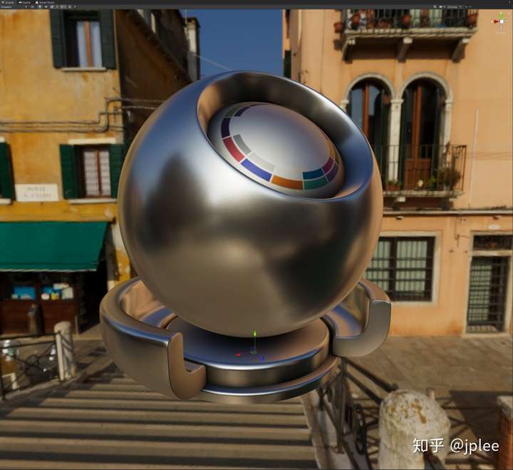
It should be noted that the AO operation structure of UPR is different from that of SP.
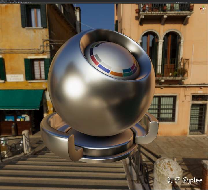
Let’s get removing of the Bloom effect.

IDT? Input device transform(IDT) :This name was deprecated in version 1.0 and has been replaced by input conversion. The process of taking an image captured from the original material that can be collected and converting the content to ACES color space and encoding specifications. There are many IDTs that are unique to each class of capture equipment and appear to have been specified by the manufacturer using ACES guidelines. It is recommended to use a different IDT for tungsten versus daytime lighting conditions. Input Transform : The current term name for Input Device Conversion (IDT) according to ACES version 1.0 or later.
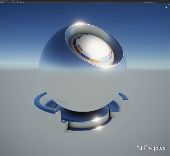
First we’ll check.Check out the result of removing Tone mapping in Unity3D.In particular, remember the density changes in the glossy and dark areas and the color of the reflectors (green and orange).
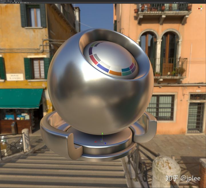
The color space is converted through ACES COLOR MATRIX, and LUT_HDR is finally generated in the post processing.